The upward pointers in figures 7 and 8 are highlighted for clarity.
Note that only one node in the tree, the rightmost node (containing the largest erttry in the sorted list), has a right pointer with a value of zero.
This is a signal that the end of the tree has been reached.
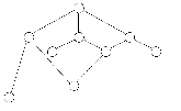
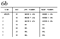
Let us look at the process of reading the sorted numbers from the tree in figure 7.
We enter the tree at the root node, which contains the integer 15.
We move ieft down the tree until we encounter the first node with a Ieft pointer of zero (which we will also refer to as NIL).
This is node number 7, the one that contains 10 as its key.
We print the value 10 and follow the right pointer back up the tree to node 2, which contains a 12.
We print the 12 and follow the right pointer of this node to node 4.
|
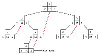
Figure 8:
Addition of a node to a binary tree.
Using the notation of figure 7, this figure shows the addition of node 8, which has a key value of 13.
The Ieft pointer of node 8 is 0, denoting no Ieft child.
The right pointer of node 8 is -4, denoting two things:
first, that node 8 has no right child;
and second, that the node whose key follows the key of node 8 in the sorted-key sequence is node 4.
The upward right pointers are shown here in cotor.
|

|
|

|
|
Figure 9:
Flowchart for subroutine FIX.
This subroutine initializes storage space in a Computer for later use as a threaded binary tree.
|
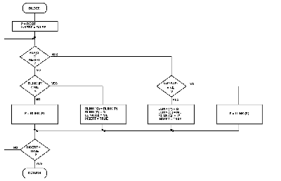
Figure 10:
Flowchart for subroutine BILDER.
This subroutine adds node Q (with key value KEY (Q)) to the existing binary tree.
|
Figure 11:
Flowchart for subroutine SEARCH.
This subroutine searches the binary tree for a node with a key value of ALPHA.
|
Node 4 has no left child, therefore we print 14 and follow the right pointer back up the tree to node 1.
At node 1, we print 15 and follow the right pointer to node 3.
Node 3 has a left child, so we move from node 3 along the left pointer to node 6.
Node 6 has no left child, so we print the contents of node 6, which is 20.
Following the right pointer of node 6 back to node 3, we print its value, 25.
Following the right pointer of node 3 to node 5, we find the 26, which has no left child.
So we print 26 and look at the right pointer of this node.
Since the right pointer is NIL, the rightmost node must have no sucessor.
This means it is the last node in the tree, so we end the sort.
This is certainly a lot of trouble--unless you want to do more than just sort your numbers once.
And it is here that the binary tree shows its greatest advantage.
In most sort procedures, if you add a number to the list to be sorted, you have to completely re-sort the new list.
But with a binary tree, all you have to do is add one node and list the tree (both of which take much less time than a complete re-sort).
Figure 8 shows the addition of one node, a 13, to be added to the tree of figure 7.
The 13, being the eighth number in our list, becomes node 8.
It is added to the tree at the bottom of the appropriate branch, necessitating the change of only one pointer in the old tree:
the left pointer of node 4 now points to node 8.
All the other pointers remain intact, thus keeping computer time to a minimum.
Best of all, no key values of nodes have been altered in the least.
Deletion of nodes from the tree is not as obvious a procedure as one might suppose.
|
It is not hard to write a subroutine that will traverse a binary tree in the proper order.
Nor is it difficult to write a subroutine to add a node to a tree--or, equivalently to add a number to a sorted list.
Deletion of nodes from the tree, however, is not as obvious a procedure as one might suppose.
Detaching the node to be deleted is simply a matter of destroying the pointers from other nodes to the undesired node.
But repair of the tree diagram--connecting nodes below the deleted node to the body of the tree--is not quite so easy.
There are several cases to be considered, all of which are handled by the subroutine DEL.
The binary-tree-sort program in listing 1 was designed as a main routine and a collection of subroutines.
A brief description of each subroutine (given below) and a flowchart describe the operation of each of the subroutine modules.
Each of the subroutines was written in structured fashion.
Although the main routine is also structured, the current listing reflects a certain amount of modification and experimentation;
in other words, it has not been rewritten for optimal structure.
|
|
|
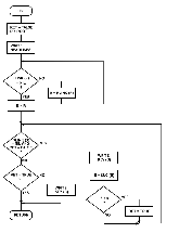
Figure 12:
Flowchart for subroutine LIST.
This subroutine traverses the binary tree in sorted key order and prints the nodes as they are encountered.
|
Figure 13:
Flowchart for subroutine SUC.
This subroutine, given for a node P, finds the number of the node that is the successor of node P in the sorted-key sequence.
|
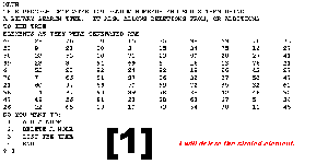
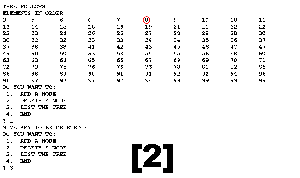
The main routine of listing 1 contains the following sequence:
an array of 100 random integers is created and used to create a sorted binary tree;
the binary tree is listed;
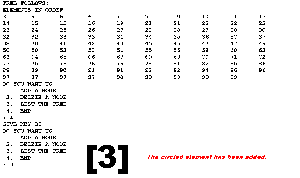
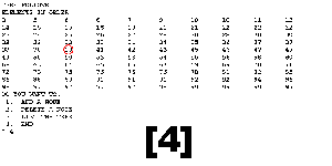
then the user is given the options of adding to the tree, listing the tree, or deleting from the tree.
All the necessary subroutines are included in this listing.
This program was originially written in FORTRAN and was later translated to BASIC, running first on a PET, then on an Apple II.
The program contains some redundancies so that the program will run as written on both machines;
the only restriction is that line 5 must be deleted before running the program on the PET.
The structured programming techniques used in writing the original FORTRAN version proved to be quite necessary when translating and debugging the BASIC version.
I feel that structured programming techniques are essential to a program of any size.
Subroutine Descriptions
FIX:
The purpose of the subroutine FIX (see flowchart in figure 9) is to initialize all the space to be used for tree nodes before the binary tree is built.
The FIX subroutine must be presented with N, the maximum number of nodes to be available to the tree.
Once the tree has N nodes, there are no provisions in this program to make additional space available.
BILDER:
Subroutine BILDER adds a new data entry to the binary tree, placing it in correct relation to the other nodes in the tree.
Within the BILDER routine, the node to be added is numbered Q and has a value of KEY(Q).
The algorithm (see flowchart in figure 10) compares the node to be added, Q, with other nodes (starting with the root node and moving down the tree) until it can be placed in proper relation to a parent node (a node that has a NIL pointer pointing to where node Q should go).
SEARCH:
The SEARCH subroutine (see figure 11) returns the node number of a key with value ALPHA.
The node number (or zero if the node is not found) is returned in the variable SEARCH.
The search done is not a linear search but rather a binary search like the one used in BILDER.
A binary search is named such because each decision halves the area to be searched.
LIST:
The LIST subroutine (see figure 12) lists the nodes of the tree in ascending key sequence by traversing the tree from its leftmost to its rightrnost node.
LIST follows an optimal path down the leftmost branch of the tree until it encounters a node the left pointer of which has value NIL;
this node contains the smallest key value.
Having found the smallest key value, LIST then calls SUC (the successor subroutine) repeatedly to find successor nodes;
key values are printed in the order they are encountered.
When a node is found that has a right pointer of value NIL, the node with the highest key value has been found, and the LIST subroutine has finished.

|
|
|
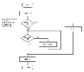
Figure 14:
Flowchart for subroutine PAR.
This subroutine finds the parent node of a given node P.
|
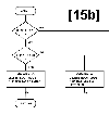
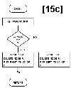
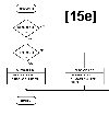
Figure 15:
Flowchart for subroutine DEL.
Figures 15a thru 15e describe the algarithm, with further description given in table 1.
Case I is executed when the node to be deleted, P, is the root node.
Case II, group A is executed when the node to be deleted, P, is the left child of a parent node.
Case II, group B is executed when the node to be deleted, P, is the right child of a parent node.
|
Case I: Node P to be deleted is the root node.
  Subcase A: Node P has no children.
      1. Set EMPTY = TRUE.
      2. Set N (the number of nodes in the tree) to zero.
  Subcase B: Node P has only a right child.
      1. Set new root equal to right link of old root.
  Subcase C: Node P has only a left child (see figure 16a).
      1. Set new root equal to the left link of the old root.
      2. Search right branch of left child of P for its
         rightmost node R. Set the right pointer of R to NIL.
  Subcase D: Node P has a left and a right child (see figure 16b).
      1. Set new root equal to the right link of old root.
      2. Search left branch of right child of P for its
         leftmost node S. (S will have a left pointer of NIL.)
         Set left pointer of S to the left child of the
         old root (that is, to point to the left subtree
         of the old graph).
      3. Search right branch of left child of P for its rightmost
         node R. Set right pointer of R to point to S.

Case II: Node P to be deleted is not the root node.
  Group A: Node P is the left child of parent node Q.
   Subcase 1: Node P has no children,
       a. Set LEFT link of parent Q to NIL.
   Subcase 2: Node P has only a right child.
       a. Set LEFT pointer of parent node Q to right child of P.
   Subcase 3: Node P has only a left child (see figure 16c).
       a. Set LEFT pointer of parent node Q to left child of P.
       b. Search right branch of left child of P for its
          rightmost node R; this node will have an upward right
          pointer to P. Assign the right pointer of R the value of
          the right pointer of P.
   Subcase 4: Node P has a left and a right child (see figure 16d).
       a. Set LEFT pointer of parent node Q to right child of P.
       b. Search left branch of right child of P for its
          leftmost node S. (S will have a left pointer of NIL.)
          Assign the left pointer of S the value of the left pointer
          of P.
       c. Search right branch of left child of P for its
          rightmost node R. Assign the right pointer of R the
          value -S.
  Group B: Node P is the right child of parent node Q.
   (Subcases 1 thru 4 are the sarne if the word RIGHT is
   substituted for the capitalized word LEFT in each subcase.)
|
|
Table 1:
Analysis of node deletion in a threaded binary tree.
This table details the operations necessary to delete a node, labeled P, from a threaded binary tree.
This table is associated with figure 15, figure 16, and listing 1.
|
|
SUC:
The SUC subroutine, shown in figure 13, when given the node numbered P, returns the value SUC, which is the number of the node that follows node P in the ascending key sequence.
If the right pointer of P, named Q, is an upward pointer (value less than zero), the absolute value of the pointer is the successor node.
If Q is a downward pointer, the leftmost child of Q is the successor node.
A SUC value of NIL is returned if node P is the rightmost node in the tree.
PAR:
The PAR subroutine, shown in figure 14, returns in variable PAR the number of the parent node of node P.
(Remember that every node in a binary tree except the root node has exactly one parent node.)
As in BILDER and LIST, a binary search starting at the root uses the values of the current node key and the key of node P to guide the search down the tree until the parent of P is found.
This method is much faster than linearly traversing the tree using the SUC subroutine.
DEL:
The DEL subroutine to delete a node from the tree is the most complicated of the subroutines presented.
This is due largely to the necessity of reestablishing the thread that runs through the tree.
The algorithm for node deletion is given in figure 15 and table 1;
the examples in figure 16 are referred to by table 1.
|

|

|

|
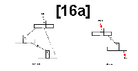
Figure 16:
Examples of node deletion.
Figures 16a thru 16d ate used to illustrate the structure of a binary tree before and after the deletion of node P;
they are referred to by table 1. A broken arrow (for example, A to R) denotes an eventual connection through zero or more intermediate children.
A dashed arrow denotes an upward right pointer to the next node in the sorted key sequence.
A gray arrow in the "after" drawing denotes a pointer that hos been changed by the deletion.
|
A Pascal Implementation
A second and somewhat different version of the binary tree program is given in listing 3.
This version does not use a threaded tree (ie: there are no upward right pointers).
Because of this, the subroutine to add a node is almost trivial, and the delete routine is greatly simplified.
This implementation is, in general, altogether nicer.
|
Listing 3:
Pascal program for sorting a binary tree.
Due to the nature of the program, the binary tree does not need to be threaded;
this simplifies most of the procedures and functions of the program.
Program details are given in the text.
This program, written to run on a Digital Equipment Corporation PDP-11/70, should run in UCSD Pascal without modification.
[Listing] |
|
|
The main change in this listing (compared to the BASIC program of listing 1) is the use of the scan procedure to traverse and list the tree.
The scan procedure uses a stack, which is maintained by the initstack and push procedures, along with the pop function.
The scan algorithm is as follows:
| 1) |
Move left along the branches of the tree, placing each node traversed onto the stack.
|
| 2) |
When a left pointer of NIL is reached, pop the stack and print what was just popped.
|
| 3) |
If you can, move right one node and go to step 1; otherwise, pop the stack, print the node popped, and repeat step 3.
|
| 4) |
Underflow of the stack represents the end of the algorithm.
|
Due to the nature of the Pascal language, the listing itself serves to document the algorithm.
In all fairness to BASIC, it must be stated that the Pascal program of listing 3 is simpler partially due to the absence of the thread running through the binary tree.
Acknowledgements
I would like to thank the Computer Corner of Amarillo, Texas, for the use of their printer to produce listings 1 and 2.
Scanned by
Werner Cirsovius
April 2012
© BYTE Publications Inc.
|
